GMAIL with own domain

Hello there, let me show you today how to create a professional business email address (e.g., info@yourdomain.tld) using free Gmail and free Cloudflare email routing service, which will allow you to use your custom domain!
This setup will forward all incoming emails to your Gmail account and also enable sending emails from your custom address via Gmail SMTP.
Prerequisites
- a domain name
- Cloudflare account (free)
- Gmail account (free)
Step 1: Set Up Cloudflare Email Routing
Add Domain to Cloudflare
Log in to Cloudflare, click "Add a Site," enter your domain, and select the Free plan.
Update Nameservers
Cloudflare will provide DNS nameservers. Go to your domain registrar and update your domain's nameservers to the ones provided by Cloudflare.
Enable Email Routing
In the Cloudflare dashboard, go to the "Email" tab and click "Email Routing".
Configure Destination Address
Under the Destination addresses tab, enter your personal Gmail address (myemail@gmail.com). Cloudflare will send a verification email to your Gmail. Open it and click the verification link.
Create Custom Address
Go to the "Routes" tab. Under "Custom addresses," click Create address.
- Custom address: Enter your desired name (e.g., info)
- Action: Select "Send to" and choose your verified Gmail address
- Configure DNS Records: Cloudflare will prompt you to add necessary MX and TXT records. Click "Add records automatically".
Step 2: Configure Gmail to Send Emails ("Send Mail As")
To reply using your custom domain email, you must use Gmail's SMTP settings.
Generate Gmail App Password
- Go to your Google Account settings (Security tab).
- Ensure 2-Step Verification is ON.
- Click on App passwords, create a new app (name it "Cloudflare Email"), and copy the 16-character password.
Add Custom Email to Gmail
- Open Gmail and go to Settings (gear icon) > Accounts and Import
- Under "Send mail as," click Add another email address
- Name: Enter your business name
- Email Address: Enter your custom email (e.g., info@yourdomain.tld)
- Treat as an alias: Keep this checked
SMTP Setup
- SMTP Server: smtp.gmail.com
- Port: 587
- Username: Your full Gmail address (e.g., myemail@gmail.com)
- Password: The 16-character App Password generated earlier
- Select "Secured connection using TLS" and click "Add Account.
Verify Setup
Google will send a confirmation code to your custom address, which will be forwarded to your Gmail inbox. Enter this code to finish.
Step 3: Set Up SPF/DMARC to Prevent Spam Issues
To ensure your emails don't go to spam, add a Sender Policy Framework (SPF) record in Cloudflare DNS:
- Type: TXT
- Name: @
- Content:
v=spf1 include:_spf.mx.cloudflare.net include:_spf.google.com ~all
Optional: Set Up Catch-All rule
If you want to receive all emails sent to any address at your domain (e.g., random@yourdomain.tld goes to info@yourdomain.tld), enable the Catch-all address rule in Cloudflare under "Email Routing" > "Routes".
Free Private ADS Blocker
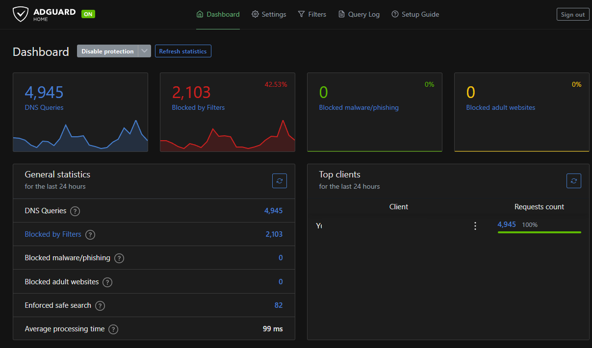
A tutorial on how to install a private ads blocker server with AdGuard Home on Oracle Cloud and Ubuntu ... all for free ...
The Server
STEP 1: Create the virtual server on Oracle
As a very first need to create the OCI (Oracle Cloud Infrastructure) instance. The oracle is giving as "always free":
- Arm-based Ampere A1 cores and 24 GB of memory usable as 1 VM or up to 4 VMs
- AMD Compute Instance: AMD based Compute VMs with 1/8 OCPU and 1 GB memory each / 2 AMD based compute VMs
- .... and many more ... see here --> oracle.com/cloud/free/
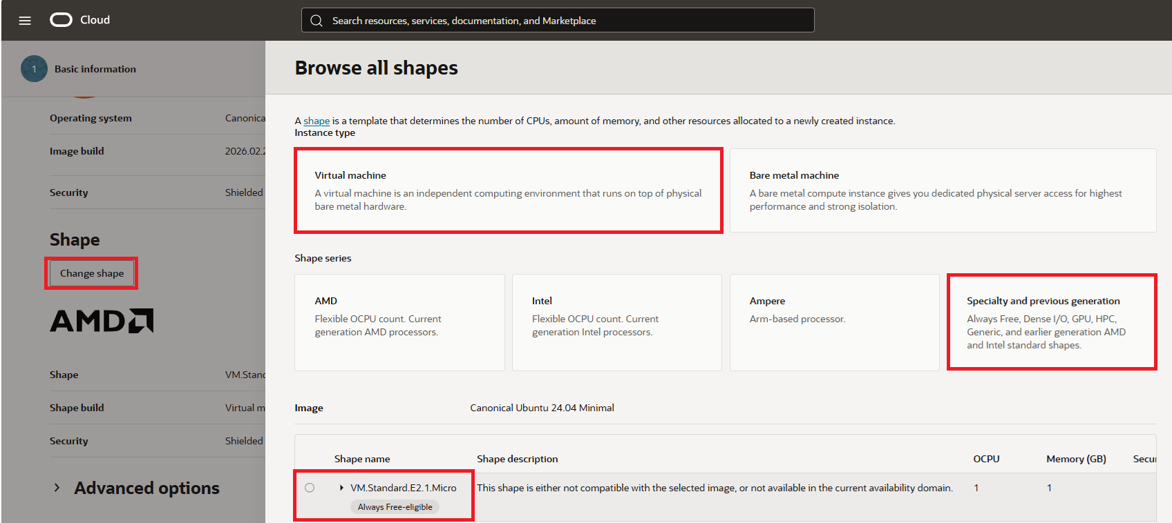
In this tutorial, we will need to use just one AMD based Compute VM with shape called "VM.Standard.E2.1.Micro".
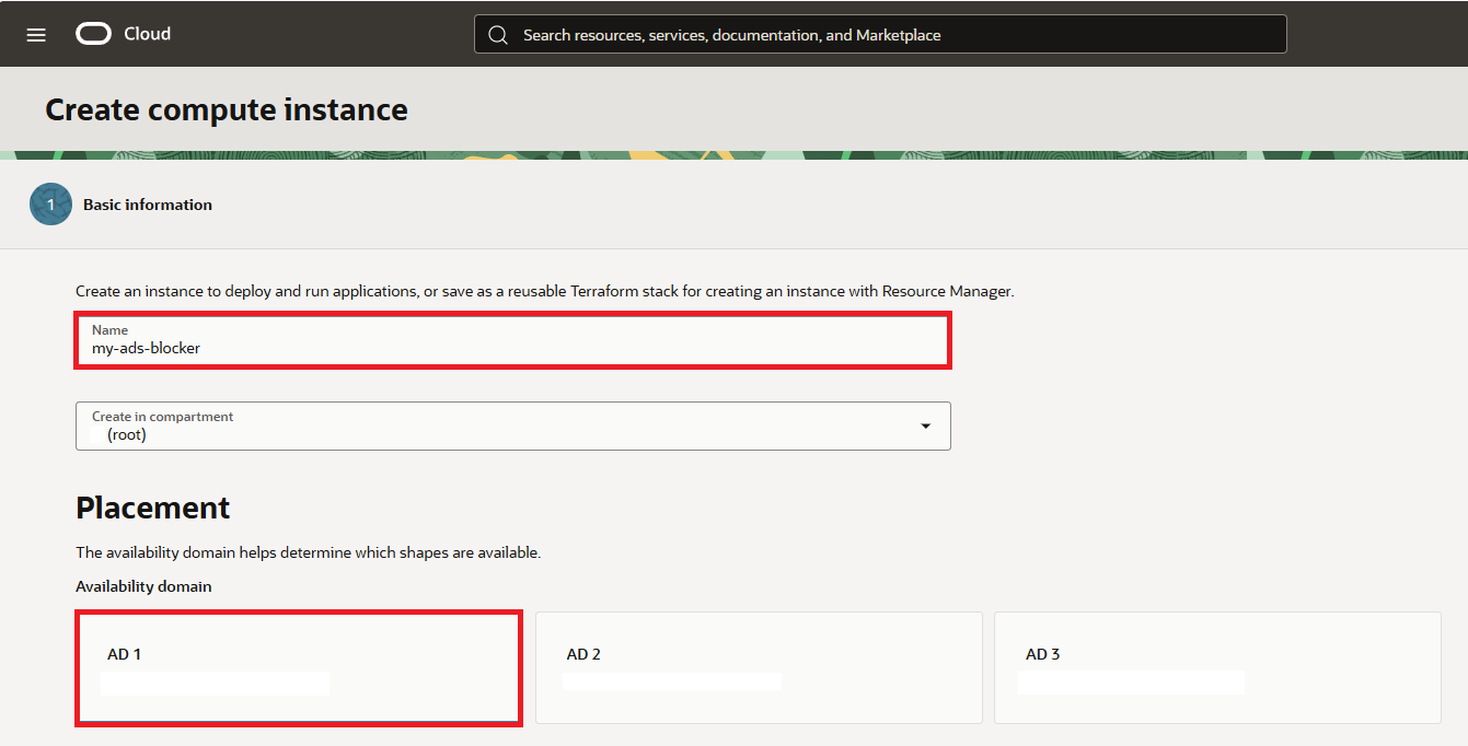
Open compute instances page and click on "Create Instance".
Type your preffered "Name" and select "Placement" option.
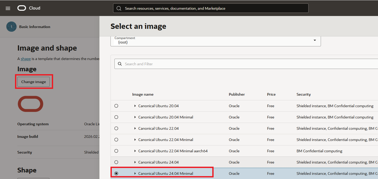
Then click on shape and select "Canonical Ubuntu 24.04 Minimal"
Next select "Virtual Machine", "Specialty and previous generation" and "VM.Standard.E2.1.Micro"
Then click on Next button to see Security options. Keep them as they are.
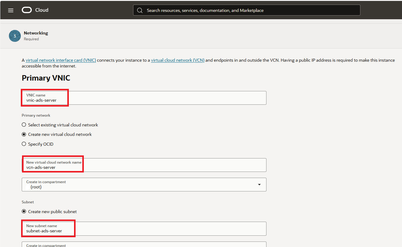
Click again next and on Networking tab setup "Primary VNIC" name, "virtual cloud network" and "subnet" name as you wish.
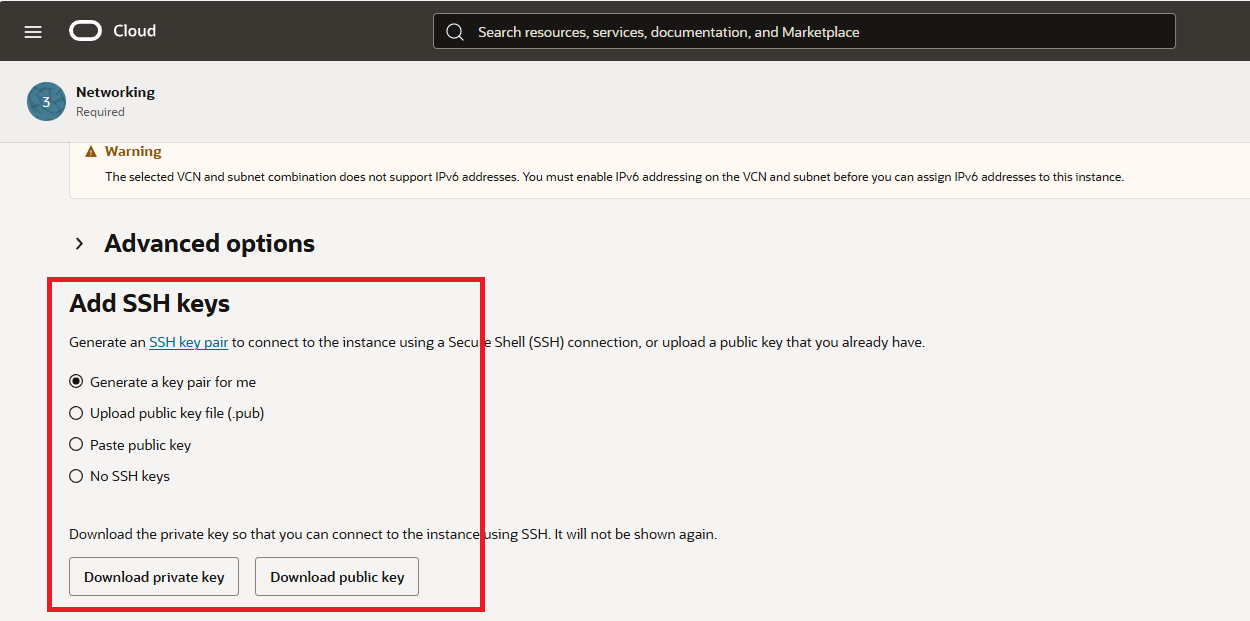
At the very bottom of the Security tab, either keep "Generate a key pair for me" or upload your exiting keys.
For the storage I kept everything as is. So you can click "Next" to review your setup and click "Create" button to create your instance.
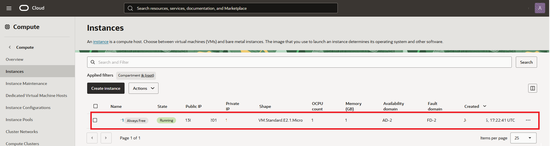
You will be then presented with compute instance just created in few minutes. Voila!
STEP 2: Configure VCN Security List
In this step we need to open ports so we can connect to our virtual machine and we will do it by editing the default security list of our VCN in Oracle panel.
Open https://cloud.oracle.com/networking/vcns
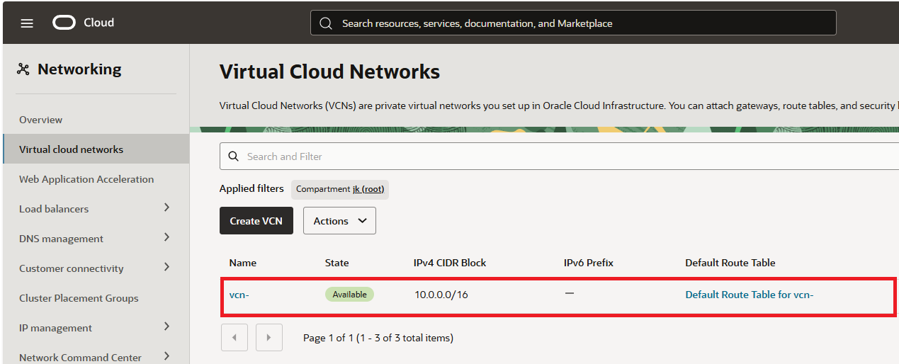
Once there open "Security" tab and click on "Default security List" of the VCN.
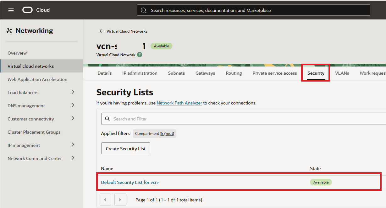
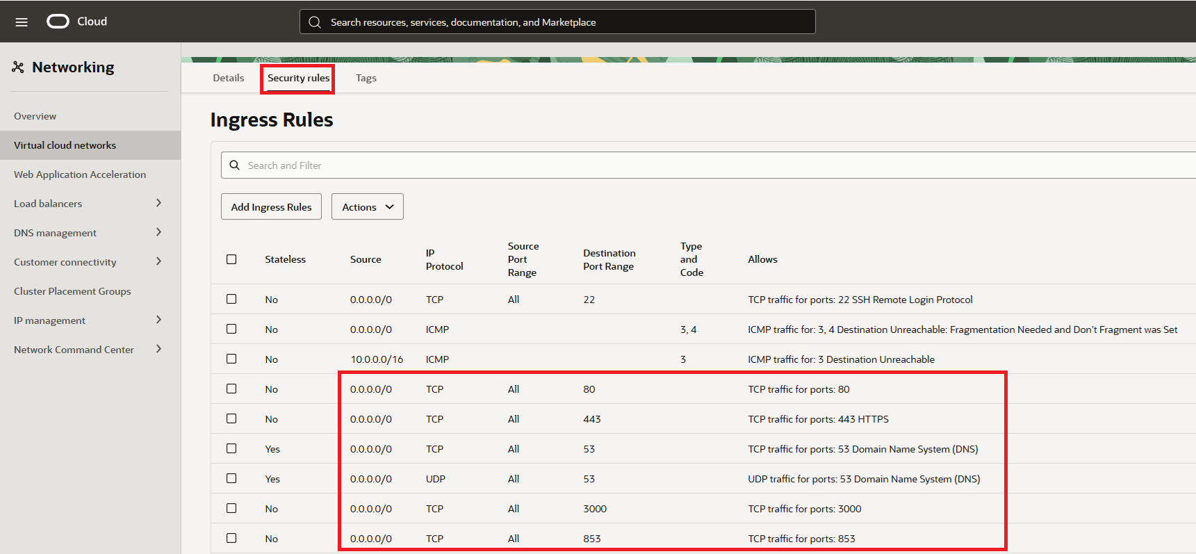
In the "Default Security List for vcn" click on "Security rules" and add below.
Ingress Rules:
- port "80" for http
- port "443" for https
- ports "53" for TCP and also for UDP
- port "3000" for intial setup - once setup - can be removed
- port "853" for mobile connection
- port "22" for SSH is already present - no need to add
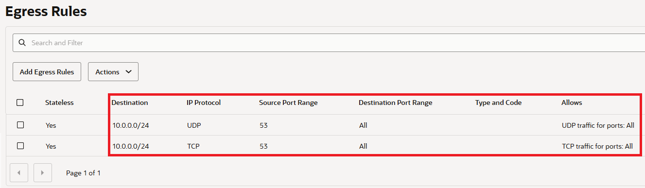
Egress Rules:
- ports "53" for TCP and also for UDP
STEP 3: Set Up the Server
SSH into your server. The default username is “ubuntu” and there is no passwd set. You will need to use the SSH keys you setup earlier.
When logged in as a first we need to make it up to date. Execute code:
sudo apt update && sudo apt upgrade -y
Once update has been done, we also need to modify the "iptables" rules:
sudo nano /etc/iptables/rules.v4
Add the following lines (only the underlined ones):
:INPUT ACCEPT [0:0]
:FORWARD ACCEPT [0:0]
:OUTPUT ACCEPT [463:49013]
:InstanceServices - [0:0]
-A INPUT -m state --state RELATED,ESTABLISHED -j ACCEPT
-A INPUT -p icmp -j ACCEPT
-A INPUT -i lo -j ACCEPT
-A INPUT -p udp --sport 123 -j ACCEPT
-A INPUT -p tcp --dport 53 -j ACCEPT
-A INPUT -p udp --dport 53 -j ACCEPT
-A INPUT -p tcp -m state --state NEW -m tcp --dport 80 -j ACCEPT
-A INPUT -p tcp -m state --state NEW -m tcp --dport 443 -j ACCEPT
-A INPUT -p tcp -m state --state NEW -m tcp --dport 853 -j ACCEPT
-A INPUT -p tcp -m state --state NEW -m tcp --dport 3000 -j ACCEPT
-A INPUT -p tcp -m state --state NEW -m tcp --dport 22 -j ACCEPT
-A INPUT -j REJECT --reject-with icmp-host-prohibited
-A FORWARD -j REJECT --reject-with icmp-host-prohibited
-A OUTPUT -d 169.254.0.0/16 -j InstanceServices
Once done, we will reboot our machine:
sudo reboot
The software
STEP 1: Install Adguard
After the server is up and running we will connect again via SSH and start the adguard installer:
curl -s -S -L https://raw.githubusercontent.com/AdguardTeam/AdGuardHome/master/scripts/install.sh | sh -s -- -v
STEP 2: Fix Bind: address already in use
There is a known issue in Ubuntu linux, therefore you will see an error on step 2:
"validating ports: listen tcp 0.0.0.0:53: bind: address already in use"
so we need to fix it. Execute code below:
sudo mkdir -p /etc/systemd/resolved.conf.d
sudo nano /etc/systemd/resolved.conf.d/adguardhome.conf
Paste the following code into the “adguardhome.conf” file:
[Resolve]
DNS=127.0.0.1
DNSStubListener=no
Save the file and execute below:
sudo mv /etc/resolv.conf /etc/resolv.conf.backup
sudo ln -s /run/systemd/resolve/resolv.conf /etc/resolv.conf
sudo systemctl reload-or-restart systemd-resolved
Now reload the installer (on port 3000) and you should no longer see the error. Continue with the setup wizard.
STEP 3: Install Certbot on Ubuntu
As a prerequesite you need to have your own domain, poiting to your server. You can order your own domain in any registrants, just setup the "A" record poiting to your server ip address:
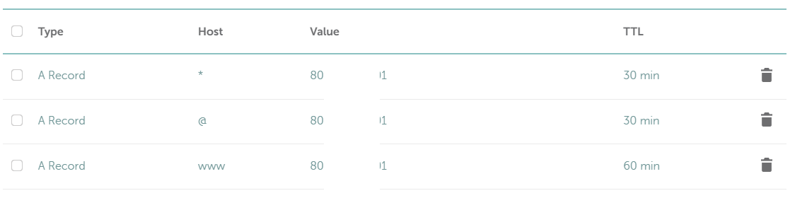
If A record is setup we will ensure that we have up to date package repositories to ensure you're installing the latest version of certbot. Execute below:
sudo apt update
then:
sudo apt install -y certbot
Once the code is installed on your server, you need to generate certificate (replace underlined with your own domain):
certbot certonly --manual --preferred-challenges=dns --email no-reply@domain.tld --server https://acme-v02.api.letsencrypt.org/directory --agree-tos -d domain.tld -d *.domain.tld
Once executed the certbot will ask you [!twice!] to add TXT record "_acme-challenge" with generated value(s) in your domain records:
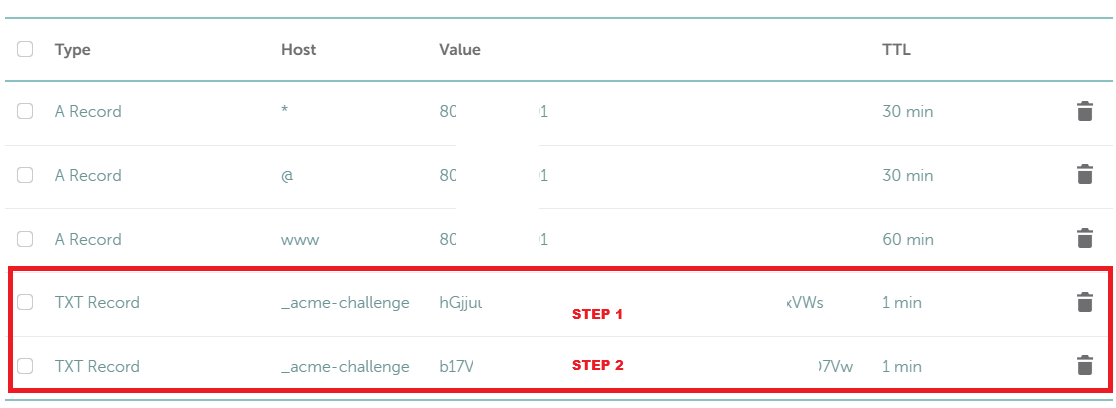 You can verify records (before clicking continue) on:
https://toolbox.googleapps.com/apps/dig/#TXT/_acme-challenge.domain.tld.
If everything works well, you've just installed & generated certificate.
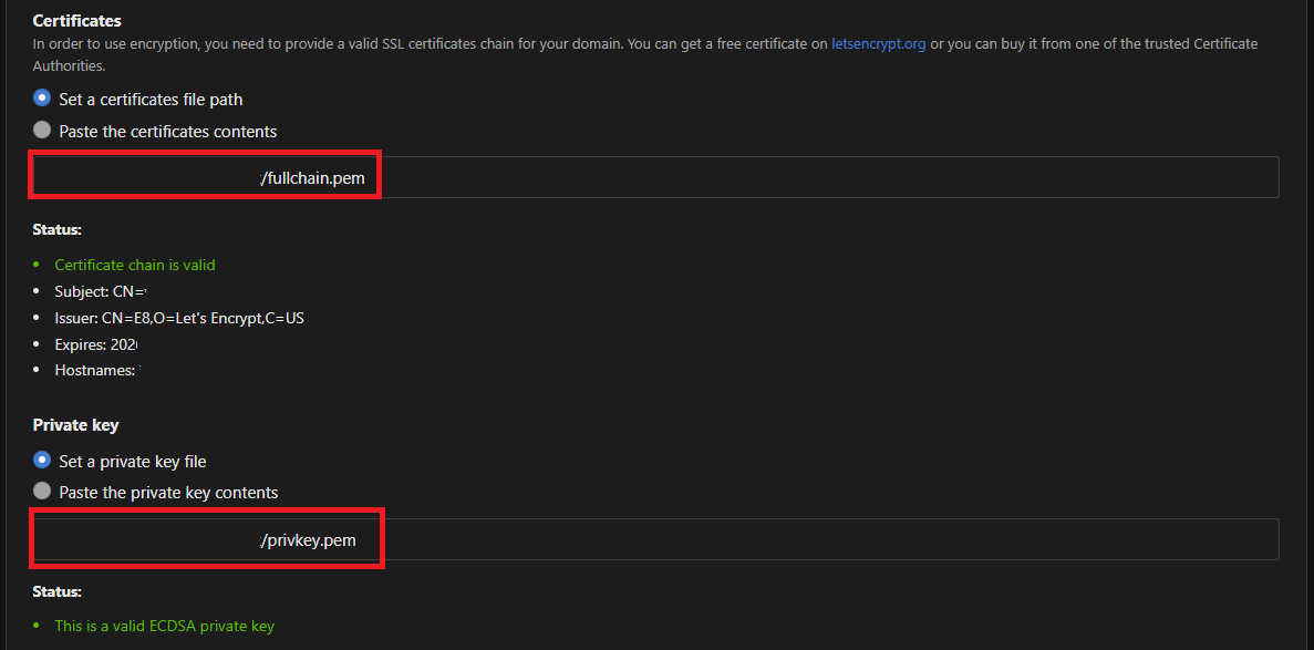
STEP 4: Setup Adguard to use secured connection
The last step is to secure your Adguard. Login to adguard and from the dashboard - go to "Settings" --> "Encryption settings" and setup below:
- Tick "Enable Encryption (HTTPS, DNS-over-HTTPS, and DNS-over-TLS)"
- Specify your domain (domain.tld) in "Server name" field
- Untick "Redirect to HTTPS automatically"
- HTTPS port "443"
- DNS-over-TLS port & DNS-over-QUIC port keep on "853"
- Set a certificates file path
- Set a private key file
 Aaaand test it!
Resources/other sites
oracle.com/cloud
adguard.com
How To Install Certbot on Ubuntu 24.04
Android "Smart" TV
Hello there! this time I will show you how you can create a smart TV from an old obsolete mobile phone, just laying in the cupboard.
Note: Your old smartphone needs to have a MHL support,
please check it in STEP 1 & Resources section at the end of this post, before continuing with order!
PARTS:
- Old Andorid smartphone supporting usb OTG/MHL (Sony Xperia Z1 Compact in my case)
- Mobile charger
- Micro USB to HDMI Adapter – [€8,19]
- HDMI cable for TV – 1,5m – [€1,88]
- Any bluetooth keyboard/mouse (*optional) - [€3,79]
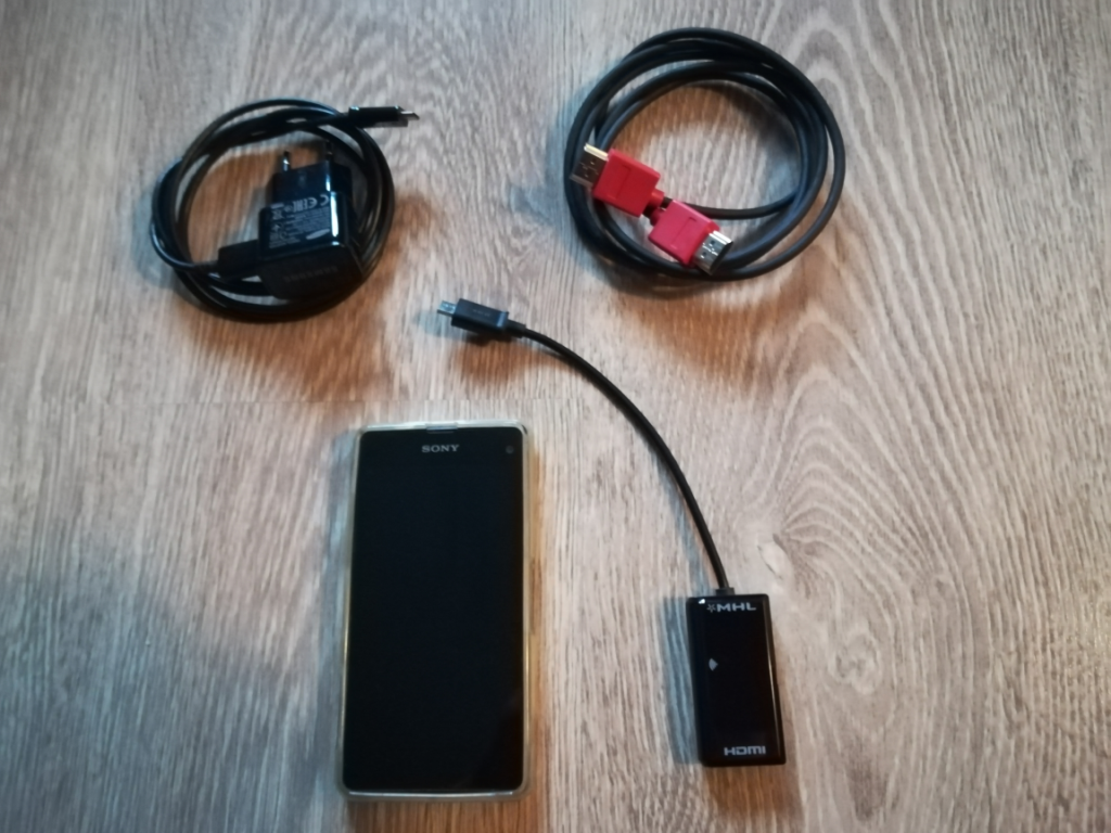
Total prize: €13,86
HOW TO
STEP 1: VERIFY IF YOU PHONE SUPPORT MHL
You can easily check if you old mobile phone support MHL on below page:
mhltech.org
If you found your device there, you can continue with ordering the parts above.
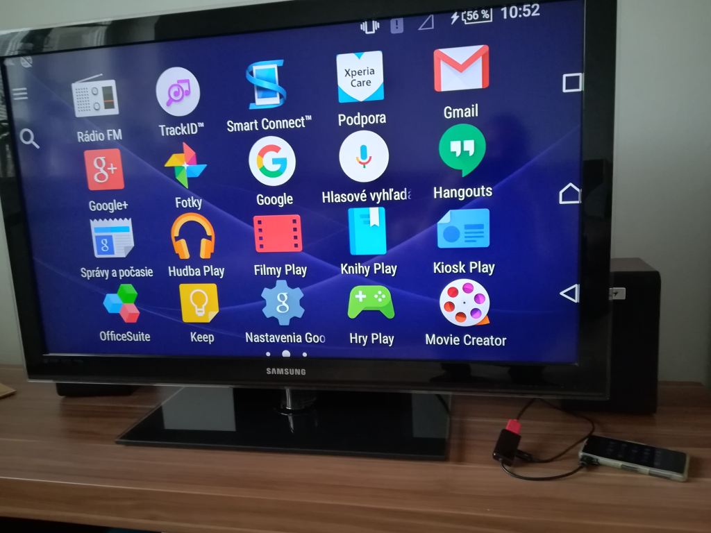
STEP 2: CONNECT YOUR MOBILE VIA MHL CABLE
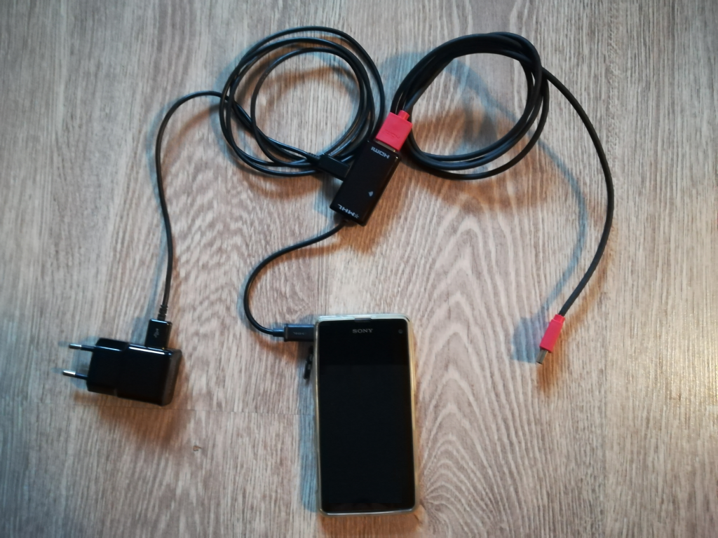
Connect the Micro USB of HDMI Adapter to your phone, HDMI cable to Micro USB and to HDMI Adapter on TV. Then adapter cable to Micro USB on HDMI Adapter.
Turn on the TV select the HDMI imput and insert the adapter to wall socket.
STEP 3: CONNECT BT KEYBOARD/MOUSE (optional)
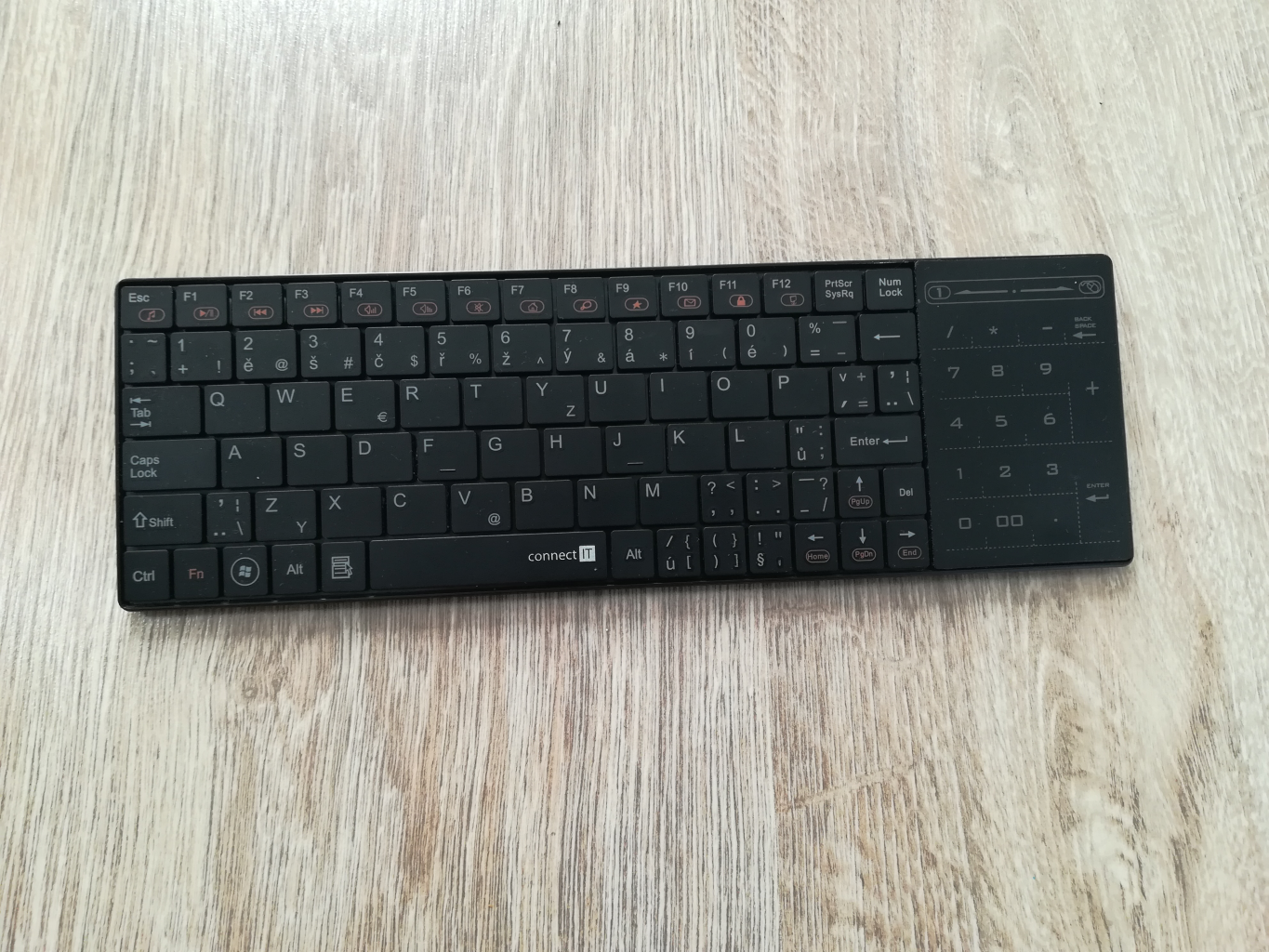
Connect your BT keyboard/mouse with your phone, so you can easily operate the mobile phone from the couch!
STEP 4: ENJOY YOUR (NEW) SMART TV!

Resources/other sites
What is MHL (Mobile High-Definition Link)? Check mhltech.org
or Wikipedia
USB Boot on Retro PC
Is it possible to boot from USB even it's not supported by BIOS? Yes it is!
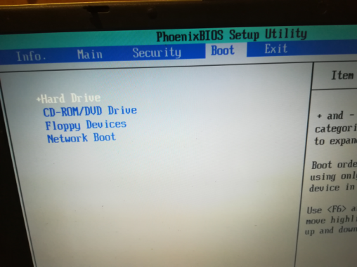
Recently I get to an ancient notebook (Acer Travelmate 2303), where USB booting from BIOS was not supported.
I was wondering if some thing like BIOS update can fix it. In my case - it can't. The options I have are: HDD, CD/DVD, Floppy or Network.
But I've found a very nice tool, which can add a booting option to the boot sequence. Thank you Elmar Hanlhofer!
OPTION 1 : Install to Boot menu on HDD
STEP 1: Download Software
To enable booting from an USB key, you will need to download a tool called Plop Boot Manager.
STEP 2: Extract and Install
Once the zip is downloaded extract the contest of the file anywhere in to the PC.
Once extracted just navigate to "Windows" folder and execute "InstallToBootMenu.bat"
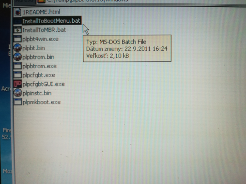 You will get a black screen with a confirmation to install. Once all set few files will be saved onto HDD and the boot.ini file will be updated.
STEP 3: Reboot PC and select PLOP Boot Manager
Once all above done, you can restart your PC and you should be able to see Plop Boot Manager during booting of your laptop/pc.
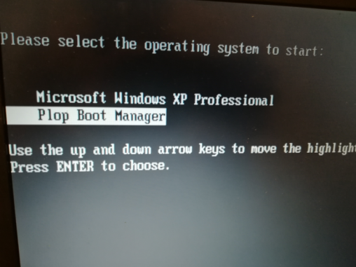 Despite that the BIOS does not have the option, you’re now able to boot anything using the USB drive. Yay!
OPTION 2: Burn Live CD/DVD
STEP 1: Download Software
To enable booting from an USB key, you will need to download a tool called Plop Boot Manager.
STEP 2: Burn to CD/DVD
Once the download is finished, extract the downloaded file. You see the image file: plpbt.iso. Burn the image to a blank CD or DVD using whatever burning software you prefer.
STEP 3: REBOOT PC AND SELECT BOOT FROM CD-ROM
Insert CD/DVD into your PC and enable booting from CD-ROM/DVD Drive
Running PLOP Boot Manager
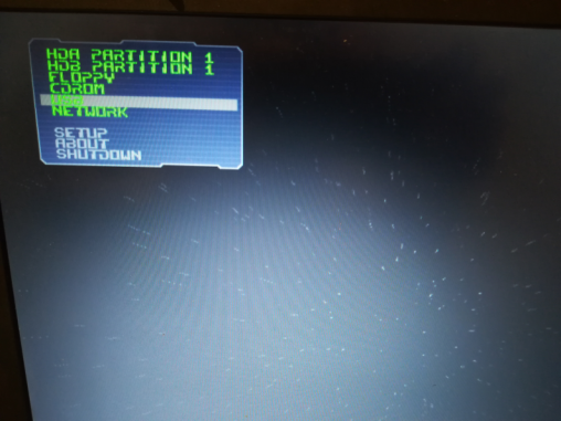
Other options to start the Boot Manager
But you have more options to run it....
Do you prefer Floppy, PCMCIA card, LAN or something else? For more ways how to run the PLOP please visit link:
LiveCD and other ways to start the Boot Manager
Resources/other sites
- Plop Boot Manager
- Boot from USB without BIOS Support via PLoP CD
- Boot From a USB Drive Even if your BIOS Won’t Let You
Turn an Old PC into a Chromebook
Recently I get to a very old laptop Thinkpad T60 (type 1951) released in 2006, which had installed Windows XP in it with 2 GB RAM.
I was wondering what I can do to make it somehow "alive" again ...
(Otherwise it can go to a trash, and that is something what I don't want to do... )
These days XP is not the best option for a notebook, so what other options do I have? Searching over the internet I found some options how to turn old pc/laptop into a Chromebook...
I've found the CloudReady and Chromium OS by ArnoldTheBat as the "most up to date" / "not dead" releases. Both looks very promising for a test.
So let's try... on this ancient notebook....
The parameters of the laptop:
Processor: Intel Core Solo processor T1300 @ 1.66GHz
RAM: 2x1GB (later I bought 2x2GB for better performance, even the 32bit system can see only 3GB)
HDD: 50GB (approx. 45 GB free after install)
Graphic card: Intel Graphics Media Accelerator 950 (Intel 945GM)
Connectivity - LAN/Wifi
USB BOOT - Yes
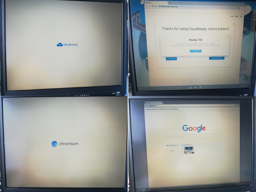
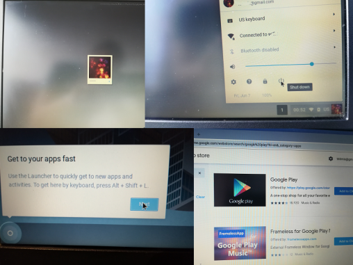
"CHROMEOS" running on OLD laptop
Top pictures showing Cloudready, bottom Chromium OS
HARDWARE
All you will need is a laptop and at least 8GB USB key.
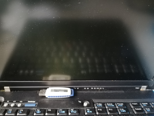
- Old PC/Laptop
- empty 8GB (or greater) USB key
SOFTWARE
- option 1: Neverware - CloudReady: Home Edition USB Maker
or:
- option 2: ArnoldTheBat - Chromium OS
For option 2 you will need also a software to load the image to USB:
balenaEtcher -- OR -- Rufus
HOW TO
STEP 1: Prepare BOOTING USB
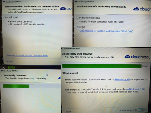
CloudReady (option 1)
Run the installer and follow on screen instructions. For this laptop I've chosen (logically) the 32-bit system.
Note: You can use any computer, preferably with Windows to create CloudReady USB - see Neverware web page for how to.
From the page: "The CloudReady USB Maker is a Windows application (.exe) that you can download directly from Neverware to guide you through the process of creating a CloudReady USB installer."
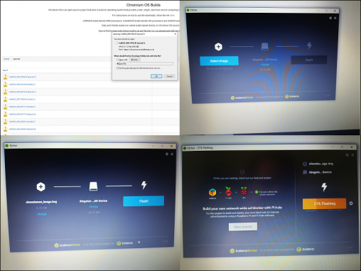
CHROMIUM OS (option 2)
Download the image from the link provided above and use Balena Etcher or Rufus to create bootable USB.
STEP 3: RUN LIVE OS
Once you have the USB ready, reboot/run the laptop, choose booting from USB. Now the laptop should read the USB and start loading the live image from USB.
STEP 4: INSTALL OS ON HDD
Once the OS is running you will need to connect to internet (wifi/lan) and setup your credentials on google. Then either click on install or do some manual steps.
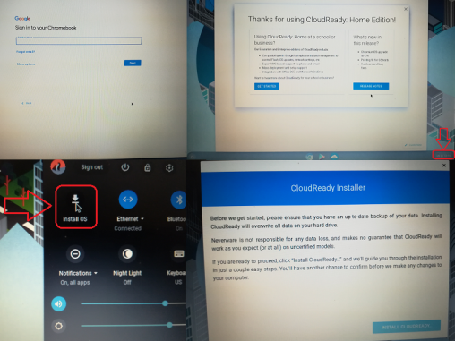
CloudReady (option 1)
For Cloudready once booted into the system, left-click on the clock at the bottom right-hand corner of the screen. Then click "Install OS".
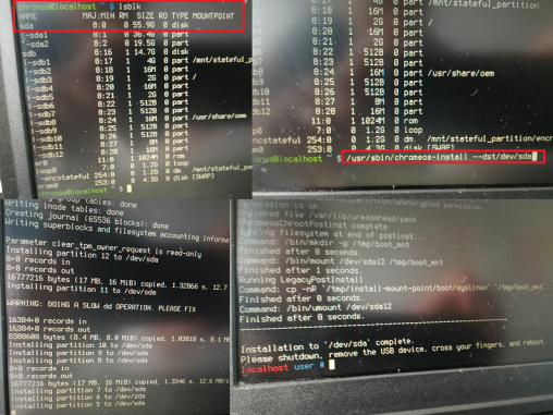
CHROMIUM OS (option 2)
For Chromium OS by ArnoldTheBat, you need to follow manual process, which will install the OS to your HDD:
1. After your computer has booted to the Chromium OS login screen, press [ Ctrl ] [ Alt ] [ F2 ]
2. Login with the chronos user (password not required)
3. Execute command lsblk to verify destination HDD
4. Execute command /usr/sbin/chromeos-install --dst/dev/sda to start install on 1st HDD disk - sda
STEP 5: REMOVE USB AND RUN CHROME OS
All done :) enjoy new Chrome OS system on your old pc/laptop.
Note: For the Thinkpad T60 the Cloudready OS was better option, as all the peripherals were immediately working. Also T60 is still in the list of supported/certified models.
More on: Certified Model Finder.
RESOURCES/OTHER SITES
- CloudReady: Install Guide
- Chromium OS | ArnoldTheBats World of Whimsy
- Getting to a command prompt on Chromium OS