Hi, welcome to my DIY project. I believe you here, because you would like to build your own “Retro Gaming Console”… Or maybe not…
Before I start with this DIY just a comment, I’ve searched over the internet to find the best and possibly cheapest option to create this. Found several resources (check bottom of this page) and my plans were inspired mainly by the console from Zach on HowChoo. What I was missing was the reset and power buttons + LED for PI status. You don’t really need any extra one. The PI have the LED so what we need to do is just to reverse it inside the cart – so the LED will be visible at the top of the cart – trough a hole.For the software I choose the RetroPie. For me it seems the best one to fit all needs and it support more then 60 systems! WOW! So… let’s start…
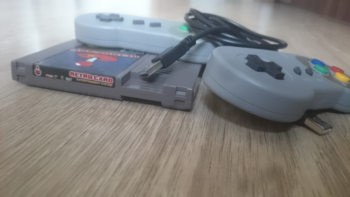
Final product:
PARTS
Console:
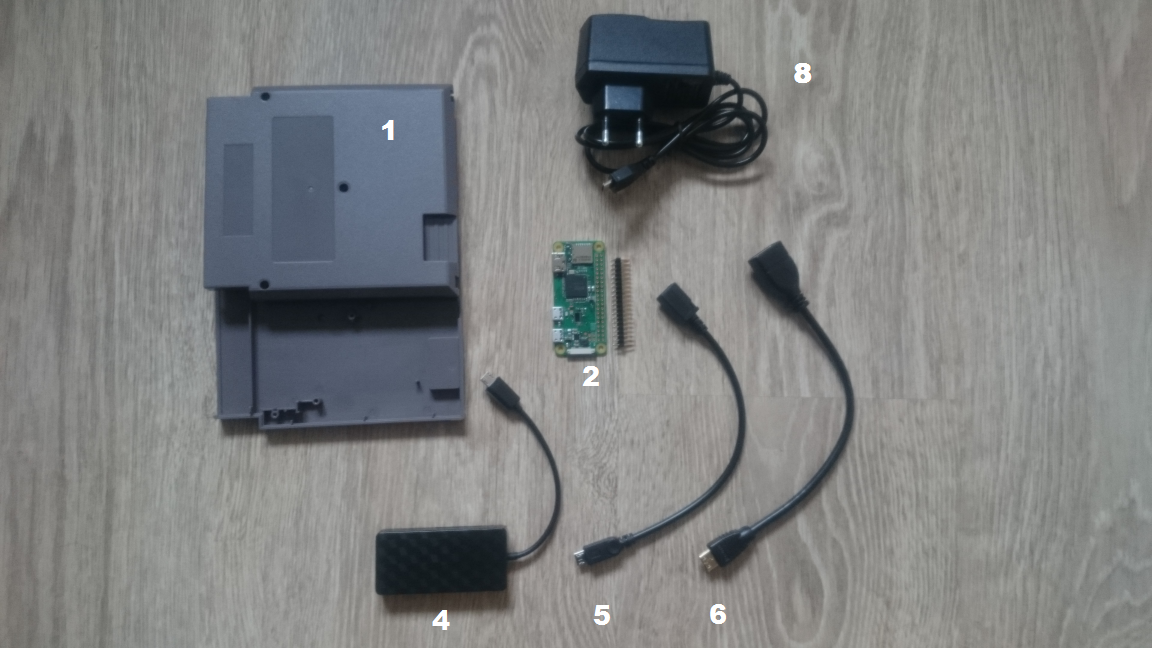 1. NES cartrige – [€3,50] – buy
2. Raspberry Pi Zero W – incl. shipping [€16,63] – buy
3. MicroSD card, 16GB – [€9,59] – local store
4. 3-port USB mini OTG Hub – [€3,34] – buy
5. Micro USB B Male Female M/F Extension – [€0,73] – buy
6. Mini HDMI Male to HDMI Female Cable – [€1,38] – buy
7. Metal Tactile Push Buttons – 5.2*5.2*4.3mm – [€0.60] – buy
Other parts:
 8. 5V 2A Micro USB Power supply – [€2,32] – buy
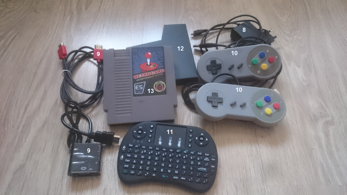
9. HDMI cable for TV – 1,5m – [€1,88] – buy — OR — HDMI to VGA adapter – [€5,32] – buy
10.Wired USB SNES Controller – [€2.70] – buy (*2nd controller optional +€2.70])
11. Wireless Mini Keyboard – [€6,83] – buy — OR —- any USB standard keyboard
12. NES cartridge dust cover (*optional) – [€0,83] – buy
13. Sticker (*optional) – [€1.99] – local store
Total prize: €60,34
Notes:
– The price above showing the totals if you don’t have anything lying at home
– Prices may differ, above showing the prices in the time of my order
HOW TO
STEP 1: TEST ALL PARTS + LOAD IMAGE
Before we will start with anything related to DIY, I would like to recommend you to connect all parts somewhere on wooden table or so and test if all works as expected.
RetroPie Image for the SD card
RetroPie First-Installation
RetroPie Supported systems
Step 2: Modifying NES cartrige
Tools:
– razor blade
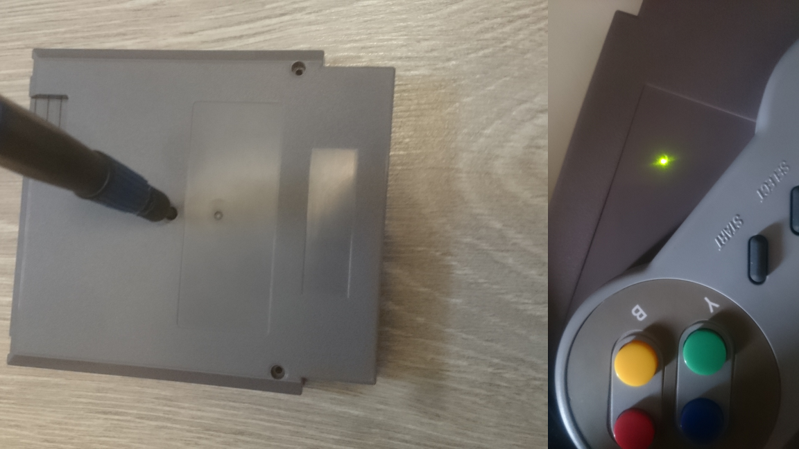
– drill
To add various ports in an accessible way, you’ll need to remove a piece of the plastic housing near the opening.Also you need to remove unneeded inside parts and drill 3 holes – 2 for power & reset buttons and one for LED from PI to see status.So take the razor blade and carefully go back and forth on the longer sides of the housing, until you feel it could go out. Then just cut the other – shorter sides. Once done cutoff also the two plastic pins inside.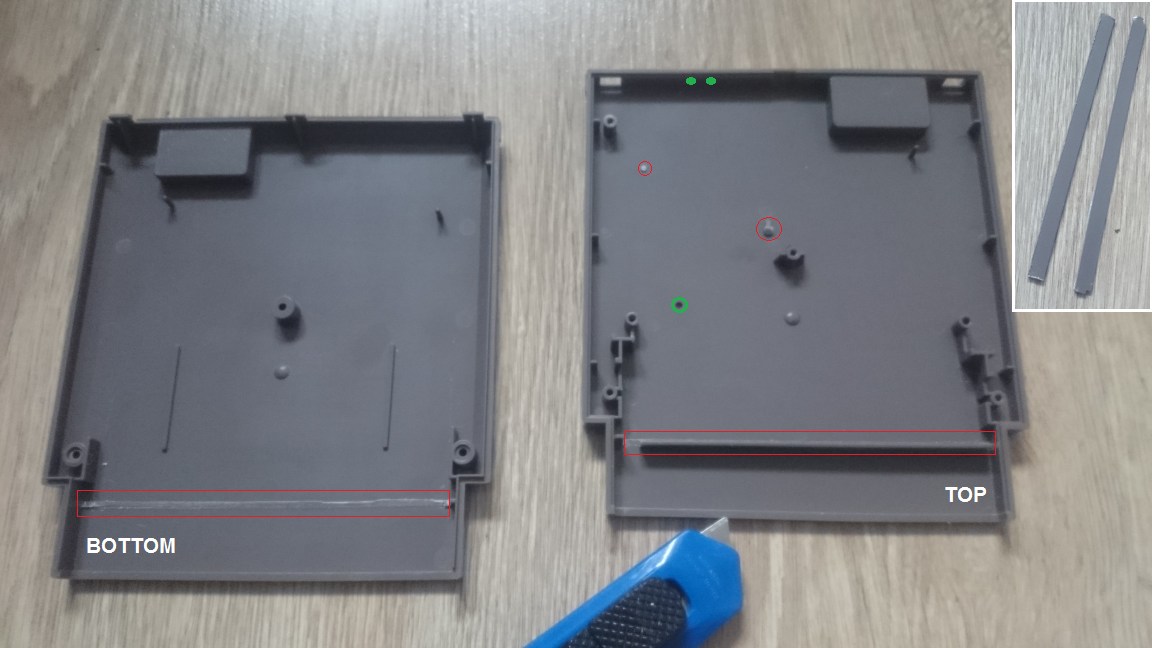 Legend: red – Parts removed with razor blade; green – 3 holes drilled
Step 3: Modifying 3-port USB mini Hub
Tools:
– razor blade
USB which I ordered got the output cable on the side, but to install it inside the NES cartridge you’ll need to move it to the back.The USB Hub does not have any screws, so you’ve just easily open it and make a similar hole in the back with razor blade. Besides that HUB had a blue LED, which was not needed, so carefully crack it (*optional). Then just add the cable at the back of it (new hole) and close it.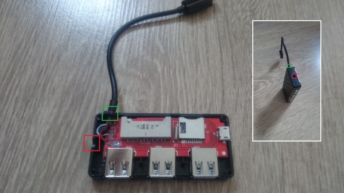 Legend: red – old hole on the side; green – new hole on the back; blue – cracked LED
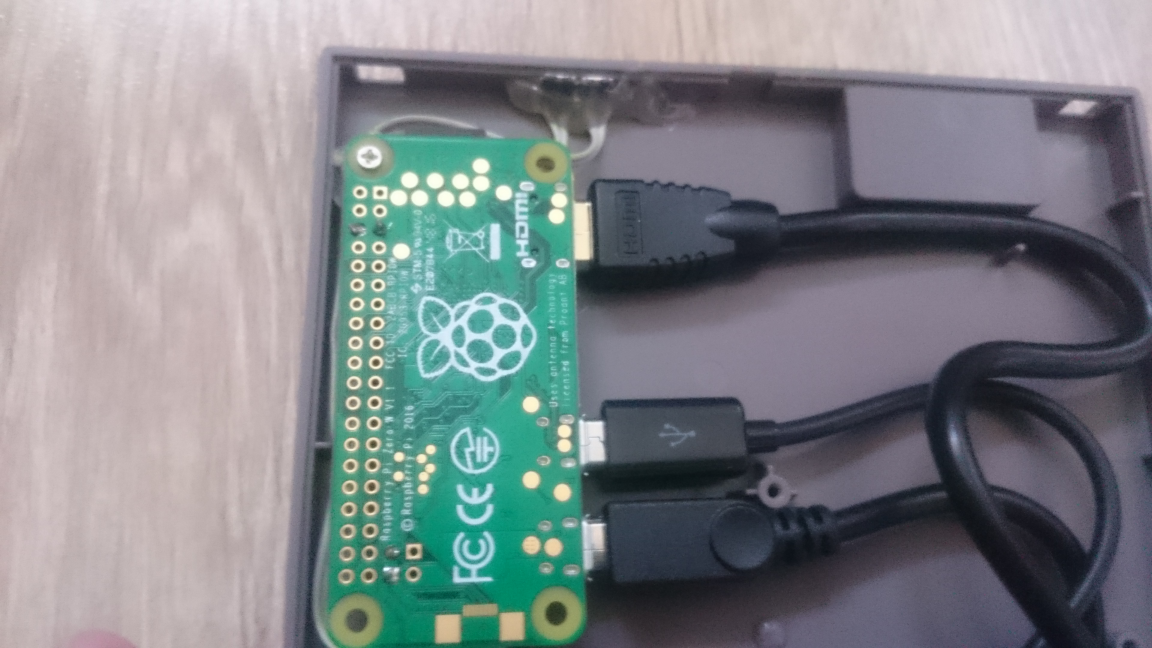
Step 4: Try how parts fits inside!
Now is the time to try PI and all the ports/cables…If all is OK, now you’ll need to solder the reset and power buttons.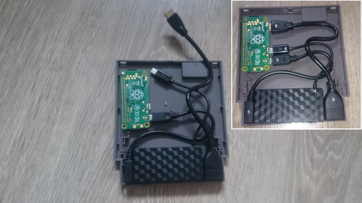
Step 5: Solder buttons to Pi and secure ALL in PLACE
Tools:
– soldering iron (+solder)
– screwdriver
– hot glue gun (+glue)
Below on the picture you can see a GPIO outputs for power on/off button and fortunately pi zero have the pins for reset – so no need GPIO.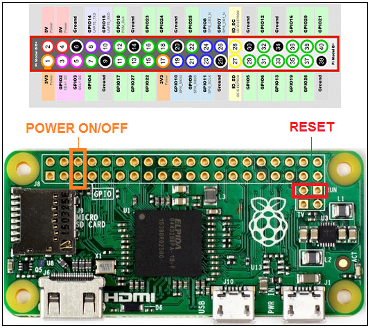
Legend: orange – power on/off button; red – reset button
STEP 6 : CODE FOR POWER BUTTON
As the Raspberry Pi Zero W does not have any power button, we need to use 2 GPIO pins (5 and 6) and a piece of code for safely shut down the PI via power button. Power button is not a must, but I really like the idea to have a power & reset hardware buttons for easy reset or turn off/stand-by.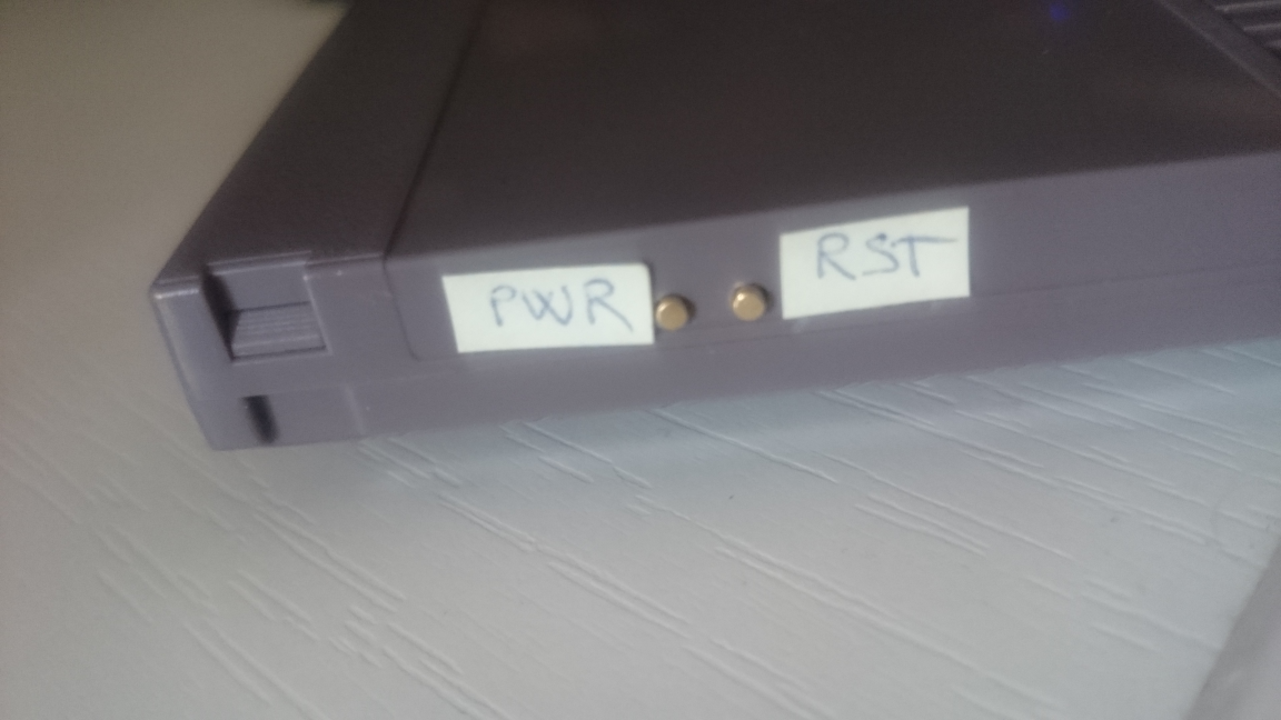 You need to create 2 files inside the PI. The easiest for me was to run the RetroPie image and push F4 to go into command prompt.
a. Create a file “listen-for-shutdown.py”:
sudo nano listen-for-shutdown.py
b. Paste/rewrite the following code into that file:
#!/usr/bin/env pythonimport RPi.GPIO as GPIOimport subprocessGPIO.setmode(GPIO.BCM)GPIO.setup(3, GPIO.IN, pull_up_down=GPIO.PUD_UP)GPIO.wait_for_edge(3, GPIO.FALLING)subprocess.call(['shutdown', '-h', 'now'], shell=False)
c. Then we need to start this script on RPI boot. So we’ll save it in “/usr/local/bin”
sudo mv listen-for-shutdown.py /usr/local/bin/
d. Make it executable:
sudo chmod +x /usr/local/bin/listen-for-shutdown.py
e. Now we need to add another script called “listen-for-shutdown.sh” that will start/stop our service. Create the script:
sudo nano listen-for-shutdown.sh
f.Enter the following code in that file and save it:
#! /bin/sh### BEGIN INIT INFO# Provides: listen-for-shutdown.py# Required-Start: $remote_fs $syslog# Required-Stop: $remote_fs $syslog# Default-Start: 2 3 4 5# Default-Stop: 0 1 6### END INIT INFO# If you want a command to always run, put it here# Carry out specific functions when asked to by the systemcase "$1" in start) echo "Starting listen-for-shutdown.py" /usr/local/bin/listen-for-shutdown.py & ;; stop) echo "Stopping listen-for-shutdown.py" pkill -f /usr/local/bin/listen-for-shutdown.py ;; *) echo "Usage: /etc/init.d/listen-for-shutdown.sh {start|stop}" exit 1 ;;esacexit 0
g. Place this file in “/etc/init.d” and make it executable.
sudo mv listen-for-shutdown.sh /etc/init.d/sudo chmod +x /etc/init.d/listen-for-shutdown.sh
h. Now we’ll register the script to run on boot.
sudo update-rc.d listen-for-shutdown.sh defaults
i. now go ahead and start it with:
sudo /etc/init.d/listen-for-shutdown.sh start
STEP 7: Test the buttons & Reassemble the cart
Tools:
– screwdriver
STEP 8: Sticker – holes
Tools:
– scissors
– thumbtack smaller
– thumbtack bigger
– toothpick
– razor blade
I’ve ordered 6 stickers ( 6 because it was on A4 paper size) and I was wondering how to make a nice small rounded holes.Unfortunately I don’t have punch machine at home (another €7 in local store), so used thumbtacks, toothpick and razor blade to carefully create holes that I need.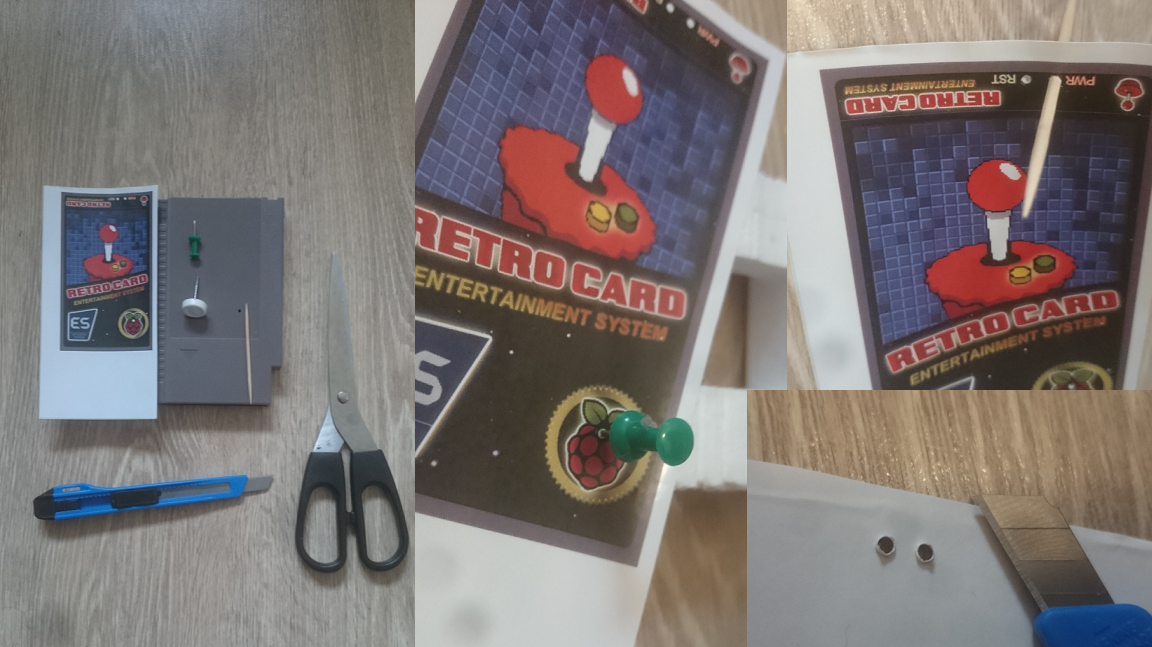
STEP 9:Sticker – Apply it
Tools:
– only your hands 🙂
In this step you need to carefully apply the sticker on the card- start from top of the card (where the buttons are). 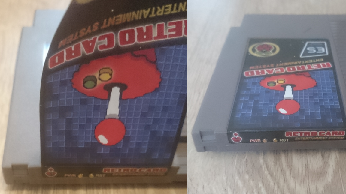
STEP 10: ALL DONE – LET’S PLAY!
Now it’s the time to connect all outside cables to the card and to you TV or monitor!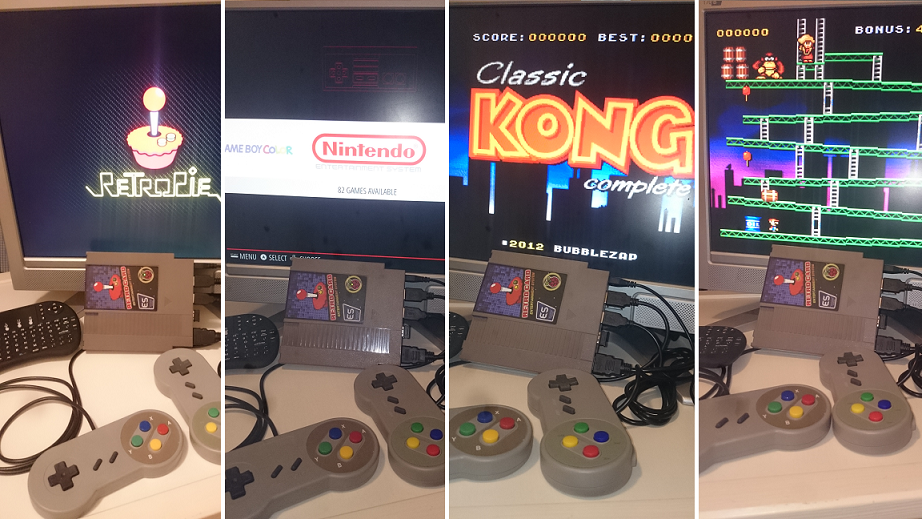 …aaaand.. Works great!
Resources/other sites
DIY NES CLASSIC
PI Cart Retropie in a NES Cartridge
Retro gaming console
Raspberry PI Zero NES Case Project
nes-cart-retropie.pdf
Build your own Raspberry PI Retro gaming rig
PI cart a Raspberry Pi retro gaming rig in an NES cartridge
How to add a power button to your Raspberry Pi
Retro console NES cartridge using Raspberry Pi Zero